LED using Arduino (lab-switch)
For my first lab, we were to design a switch that turns an LED on. However, due to my understanding of how to do the labs, I created a circuit with an LED light on an Arduino. On watching the videos linked on the resources page of the physical computing class, and with the help of some basic knowledge from the ITP camp, I designed my circuit.
I first connected the red and black wires to the Arduino and the breadboard, for the digital output (13) and ground respectively. On doing that, I connected a 220 Ohm resistor on the same column of the red wire to connect them solderless. The other end of the resistor was then connected to the positive side (longer side) of the LED light, to let the current flow from positive to negative. The shorter side of the LED, i.e. the negative terminal was then connected onto the same column of the black wire which eventually takes the charge to the ground.
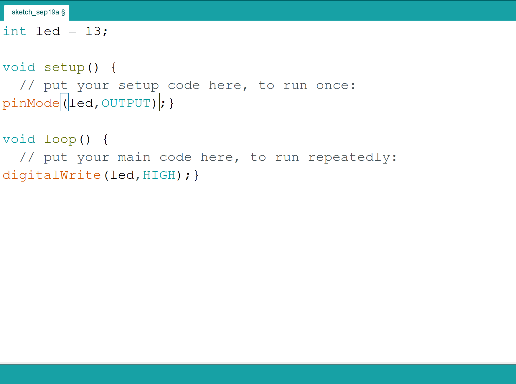
After arranging my circuit on the breadboard, I connected my Arduino’s USB cable to my laptop. On opening the desktop application of Arduino, I came across two ready functions, void setup () and void loop (). This concept was similar to the p5js’ functions of function setup () and function draw (). I set up a variable for the digital out pin int led = 13, which meant that the digital output was set at pin 13. Under void setup (), I added pinMode (Led, OUTPUT) that meant that the LED on the pin is an output for the circuit. And the final line I added under void loop () was digitalWrite (led, HIGH) which meant to turn the LED light “on”.
On then verifying and uploading the code, my LED was emitting a lovely red light!


